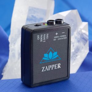

This page explains how to make a Zapper according to Hulda Clark. This is the simplest and most efficient version that works just like the original, and the battery lasts much longer. We make no therapeutic claims for this device, and it has only an experimental purpose. We also provide a ready-to-use version for those who don’t want to spend time building their own zapper.
Parts and materials
- A hexagonal CD4069 inverter
- 1 resistor 1M, 1 resistor 220k, and 1 resistor 1k 1M, 220k, 1k.
- 1 capacitor 100pf
The Zapper is a very low power device, so 1/4 watt resistors and 25 volt capacitors will be sufficient.
NOTE: The exact values of most components can be replaced depending on what you have on hand. The 220k resistor and 100pf capacitor determine the frequency of the Zapper, which can vary quite widely depending on Dr. Clark. The 1M must remain relatively large compared to the 220K to provide a reasonably symetrical waveform. The 1k must be kept at 10 or 20% of the value to provide reasonable current limiting. (If you know what you are doing and want to try different output currents, you can adjust this accordingly.
The following parts can be replaced according to your preference, but something like this will be necessary:
- Welding board
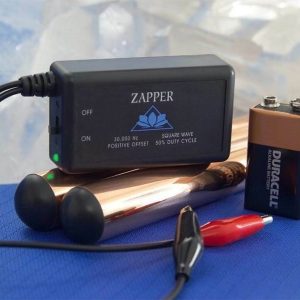
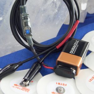
- 9 Volt Battery
- 4 sets of alligator clips Radio Shack link
- 2 pieces of copper pipe (handles)
The instructions
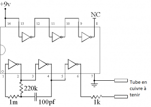
Connect the components to the solderless power supply plate according to the diagram. Make sure that none of the wires touch each other. Connect pin 14 of the chip to the positive terminal of the battery and pin 7 to the negative terminal, using clamp cables or other appropriate connectors. Attach the two handles with two additional clamp cables (one goes to ground on pin 7, the other to the free end of the 1k resistor).
Schematic diagram
The above instructions are clearly not the only way to do this. You can, for example, solder all components directly to a 14-pin socket or to an electronic infusion board, as we do in our ready-to-use version. This is much more time consuming and difficult for most people, so we recommend a breadboard. As mentioned above, not all resistors and capacitor need to be the exact values mentioned here to make a functional Zapper. However, any variation in capacitance or resistance will affect the output frequency. There are frequency and power consumption limits that the chip can handle, so do not deviate too far from the specified values.
If you have access to an oscilloscope, you can use it to check your output frequency.